The machine has been designed and built in accordance with the Machinery Directives 89/392/EEC and 2006/42/EC that include the fundamental safety requirements. The chipper must have a sound and standardized safety and operating handle. The CE mark and the Declaration of Conformity are based on the highest safety standards and on a Hazard Identification and Risk Assessment (HIRA) so that the residual risks are included in this manual. The use of the wood chipper is based on a 540 rpm drive of the power take-off (PTO).
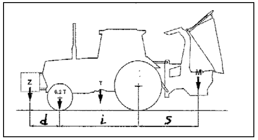
For conveying the wood chipper with a tractor, the tractor must be aligned with the chipper in accordance with the calculation below:
Z= ((M x s) – (0.2 x T x i)) / (d + i)
Where M ≤ 0.3 T
The machine manual must be kept with the chipper and operators must study this manual so that they know what is allowed and what is not allowed with the machine. The operator must also be aware of the safety instructions and be up-to-date regarding the maintenance instructions. If the machine manual is missing, the operator must report this to the employer. If there is a residual risk, a warning decal will have been stuck.
The chipper complies with the generally recognized safety requirements in accordance with the Machinery Directive 2006/42/EC that includes UNI EN 1553, UNI EN 13525 and UNI ENISO 11684 and is provided with the CE mark accordingly.
Nevertheless, the use of the machine may lead to risks for the user or third parties or damage may occur to the machine, the material and/or people. The owner of the chipper must make sure that every operator is familiar with the operation of the machine because of safety reasons. The specifics should be in accordance with this User Manual.
Carefully follow the instructions in this manual and of the manufacturer, i.e. Boxer.
 |
 |
 |
 |
 |
 |
 |
Study the manuals of the tractor and the chipper before starting to work with the machine. Especially the safety instructions and correctly safeguarded fastenings between the wood chipper and tractor are of essential importance for a proper and safe working method.
 |
 |
 |
Tools must be used for this so as not to injure hands on the sharp blades.
Daily Check
 |
Check after the first ten operational hours
  |
Check after 50 operational hours
Check after 150 operational hours or annually
 |
 |
 |
 |
 |
 |
If the chipper is no longer suitable for further use, the environmentally harmful parts such as strings, bearings, etc. must be disassembled.
Each of the sorted materials must be offered separately to the relevant authorities/companies.
The technical file, detailed drawings, structural calculations and relevant standard sheets may be available for inspection at the office of the supplier or manufacturer.

|
No. |
Part no. |
Description |
Quantity |
|
1 |
WCM8‐00011 |
WELDED WOOD CHIPPER UNDERFRAME |
1 |
|
2 |
WCM8‐00017 |
REAR COVER |
1 |
|
3 |
GB97.1‐85 |
M12 WASHER |
26 |
|
4 |
GB97.1‐85 |
M8 WASHER |
10 |
|
5 |
GB97.1‐85 |
M16 WASHER |
1 |
|
6 |
GB97.1‐85 |
M20 WASHER |
2 |
|
7 |
GB97.1‐85 |
M10 WASHER |
4 |
|
8 |
GB5782‐86 |
M12 X 130 BOLT |
9 |
|
9 |
DIN985‐87 |
M12 NUT |
13 |
|
10 |
DIN985‐87 |
M8 NUT |
4 |
|
No. |
Part no. |
Description |
Quantity |
|
11 |
DIN985‐87 |
M16 NUT |
1 |
|
12 |
DIN985‐87 |
M20 NUT |
2 |
|
13 |
DIN985‐87 |
M6 NUT |
4 |
|
14 |
DIN985‐87 |
M10 NUT |
4 |
|
15 |
GB8783‐86 |
M10 X 30 BOLTS |
4 |
|
16 |
GB8783‐86 |
M8 X 20 BOLTS |
2 |
|
17 |
GB8783‐86 |
M8 X 25 BOLTS |
4 |
|
18 |
GB8783‐86 |
M6 X 20 BOLT |
4 |
|
19 |
WCM8‐00163 |
BAFFLE |
1 |
|
20 |
WCM8‐00013 |
WORM WHEEL GEARBOX COVER |
1 |
|
No. |
Part no. |
Description |
Quantity |
|
21 |
GB93‐87 |
SPRING WASHER |
4 |
|
22 |
WCM8‐00033 |
INSPECTION HATCH |
1 |
|
23 |
WCL5‐00105 |
RUBBER WASHER |
1 |
|
24 |
WCM8‐00104 |
PRESSURE PLATE |
1 |
|
25 |
WCM8‐00188 |
REMOVAL PLATE |
1 |
|
26 |
WCL5‐00133 |
LOCKING PIN |
1 |
|
27 |
‐ |
SMALL R-PIN |
1 |
|
28 |
WCL5-00101Ke |
FASTENING PIN |
2 |
|
29 |
200.56.011. |
COMBINATION PIN |
2 |
|
30 |
WCL8‐00110 |
PLASTIC COVER |
2 |
|
No. |
Part no. |
Description |
Quantity |
|
31 |
WCL8‐00111 |
PRESSURE PLATE |
2 |
|
32 |
WCM8‐02011 |
WELDED WOOD CHIPPER HOUSING |
1 |
|
33 |
WCL8‐02101 |
BOTTOM BLADE |
1 |
|
34 |
GB7O.3‐2000 |
M10 X 35 BOLT |
4 |
|
35 |
WCM8‐00166 |
BOTTOM PLATE HOLDER |
1 |

|
No. |
Part no. |
Description |
Quantity |
|
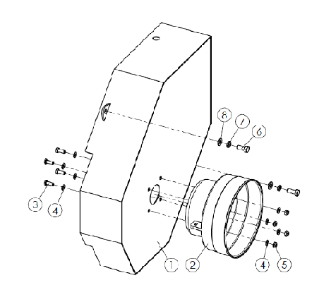
1 |
WCM8‐00015A |
DISCHARGE SPOUT |
1 |
|
2 |
WCM8‐00042 |
TIGHTENING NUT |
2 |
|
3 |
GB923‐88 |
M10 NUT |
2 |
|
4 |
GB97.1‐85 |
M10 WASHER |
4 |
|
5 |
GB97.1‐85 |
M8 WASHER |
16 |
|
6 |
WCM8‐10103 |
DISCHARGE COVER |
1 |
|
7 |
GB12‐88 |
M10 X 25 BOLTS |
4 |
|
8 |
DIN985‐87 |
M8 NUT |
8 |
|
9 |
GB5783‐86 |
M8 X 35 BOLT |
2 |
|
10 |
GB5783‐86 |
M8 X 30 BOLTS |
6 |
|
No. |
Part no. |
Description |
Quantity |
|
11 |
AM60.01.110 |
VEER |
1 |
|
12 |
GB119‐86 |
B4 X 28 PIN |
1 |
|
13 |
WCM8‐10104 |
LOCKING PIN |
1 |
|
14 |
WCM8‐00038A |
HANDLE LOCKING PIN |
1 |
|
15 |
WCM8‐00041 |
BRACKET LOCKING PIN |
1 |
|
16 |
WCM8‐10101 |
PRESSURE PLATE |
2 |
|
17 |
WCM8‐10102 |
SPACER |
1 |
|
18 |
WCM8‐00036A |
DISCHARGE SPOUT WELDED PIECE |
1 |
|
No. |
Part no. |
Description |
Quantity |
|
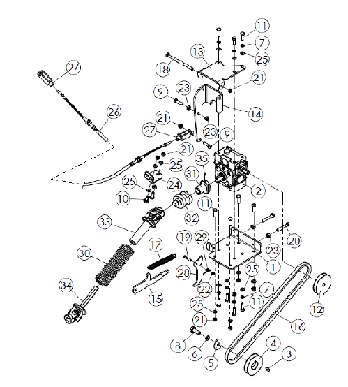
1 |
WCM8‐00187 |
WORM WHEEL GEARBOX SUPPORT PLATE |
1 |
|
2 |
QIAKY01‐91 |
WORM WHEEL GEARBOX |
1 |
|
3 |
GB1096‐2003 |
6 X 14 FLAT PIN |
1 |
|
4 |
WCL8‐00130 |
BELT PULLEY |
1 |
|
5 |
MZ105.115 |
WASHER |
1 |
|
6 |
GB93‐87 |
M12 SPRING WASHER |
1 |
|
7 |
GB93‐87 |
M8 SPRING WASHER |
7 |
|
8 |
GB5783‐86 |
M10 X 30 BOLTS |
1 |
|
9 |
GB5783‐86 |
M8 X 30 BOLTS |
2 |
|
10 |
GB5783‐86 |
M8 X 20 BOLTS |
2 |
|
No. |
Part no. |
Description |
Quantity |
|
11 |
GB5783‐86 |
M8 X 25 BOLTS |
11 |
|
12 |
24PMF.03.105 |
BELT PULLEY |
1 |
|
13 |
WCM8‐00183 |
SUPPORT PLATE |
1 |
|
14 |
WCM8‐00182 |
DRAW PLATE |
1 |
|
15 |
WCM8‐00122 |
LOCKING PLATE |
1 |
|
16 |
GB11544‐97 |
A991 BELT |
1 |
|
17 |
WCM8‐00121 |
VEER |
1 |
|
18 |
GB5782‐86 |
M8 X 120 BOLT |
1 |
|
19 |
GB5782‐86 |
M6 X 30 BOLT |
1 |
|
20 |
GB5782‐86 |
M8 X 50 BOLT |
2 |
|
No. |
Part no. |
Description |
Quantity |
|
21 |
DIN985‐87 |
M8 NUT |
8 |
|
22 |
DIN985‐87 |
M6 NUT |
1 |
|
23 |
GB6170‐86 |
M8 NUT |
4 |
|
24 |
WCM8‐00181 |
LOCKING BASE |
1 |
|
25 |
GB97.1‐85 |
M8 WASHER |
15 |
|
26 |
WCM8‐00022 |
LOCKING CABLE |
1 |
|
27 |
24PMF.03.112 |
CONNECTION |
2 |
|
28 |
WCM8‐00189 |
LOCK CANCEL PLATE |
1 |
|
29 |
WCM8‐00190 |
VEER |
1 |
|
30 |
24PMF.03.109‐1 |
VEER |
1 |
|
No. |
Part no. |
Description |
Quantity |
|
31 |
24PMF.03.107 |
INNER COUPLING CENTER BOSS |
1 |
|
32 |
24PMF.03.108 |
OUTER COUPLING CENTER BOSS |
1 |
|
33 |
24PMF.03.017 |
OUTER SHAFT |
1 |
|
34 |
24PMF.03.018 |
INNER SHAFT |
1 |
|
35 |
GB78‐2000 |
M5 X 8 BOLT |
1 |
|
No. |
Part no. |
Description |
Quantity |
|
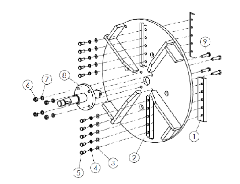
1 |
WCM8‐01101A |
CHIPPER BLADE |
2 |
|
2 |
WCM8‐01010A |
FLYWHEEL |
1 |
|
3 |
GB97.1‐85 |
M10 WASHER |
10 |
|
4 |
GB93‐87 |
M10 WASHER |
10 |
|
5 |
GB5783‐86 |
M10 X 25 BOLTS |
10 |
|
6 |
GB6170‐86 |
M12 NUT |
4 |
|
7 |
GB93‐87 |
M12 WASHER |
4 |
|
8 |
WCL8‐01011A |
FLYWHEEL SHAFT |
1 |
|
9 |
GB5782‐86 |
M12 X 50 BOLT |
4 |
|
No. |
Part no. |
Description |
Quantity |
|
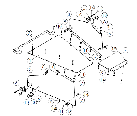
1 |
WCM8‐00116 |
BOTTOM PLATE |
1 |
|
2 |
WCM8‐00117 |
RIGHT COVER |
1 |
|
3 |
WCM8‐00118 |
LEFT COVER |
1 |
|
4 |
WCM8‐00119 |
TOP PLATE |
1 |
|
5 |
WCM8‐00193 |
CONNECTING PLATE |
2 |
|
6 |
WCM8‐00194 |
BRACKET FOR LOCKING CABLE |
1 |
|
7 |
WCM8‐00023 |
LOCKING HANDLE |
1 |
|
8 |
GB97.1‐85 |
M8 WASHER |
12 |
|
9 |
GB97.1‐85 |
M10 WASHER |
26 |
|
10 |
GB5783‐86 |
M8 X 20 BOLTS |
6 |
|
No. |
Part no. |
Description |
Quantity |
|
11 |
GB5783‐86 |
M10 X 25 BOLTS |
14 |
|
12 |
GB5783‐86 |
M10 X 30 BOLT |
2 |
|
13 |
DIN985‐87 |
M8 BOLT |
6 |
|
14 |
DIN985‐87 |
M10 NUT |
14 |
|
15 |
WCL8‐00120 |
FASTENING PLATE |
2 |
|
16 |
GB6170‐86 |
M10 NUT |
4 |
|
No. |
Part no. |
Description |
Quantity |
|
1 |
WCM8‐03011 |
DRIVE BELT COVER |
1 |
|
2 |
FM120.00.401 |
POWER TAKE-OFF SHAFT COVER |
1 |
|
3 |
GB5783‐86 |
M8 X 20 BOLTS |
4 |
|
4 |
GB97.1‐85 |
M8 WASHER |
8 |
|
5 |
DIN985‐87 |
M8 NUT |
4 |
|
6 |
GB5783‐86 |
M10 X 25 BOLTS |
2 |
|
7 |
GB93‐87 |
M10 SPRING WASHER |
2 |
|
8 |
GB97.1‐85 |
M10 WASHER |
2 |
|
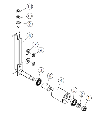
No. |
Part no. |
Description |
Quantity |
|
1 |
GB6184‐2000 |
M16 NUT |
1 |
|
2 |
GB9701‐85 |
M16 WASHER |
1 |
|
3 |
GB276‐1994 |
BEARING 104 |
2 |
|
4 |
WCL8‐00106 |
CENTER BOSS |
1 |
|
5 |
WCL5‐00107 |
SPACER |
1 |
|
6 |
DIN985‐87 |
M10 NUT |
2 |
|
7 |
GB96.2‐2002 |
WASHER10 |
2 |
|
8 |
WCL5‐00016 |
SUPPORT FOR CENTER BOSS |
1 |
|
9 |
GB97.1‐85 |
M12 WASHER |
1 |
|
10 |
GB6170‐86 |
M12 NUT |
2 |