BoxerAgri welcomes you to the growing family of new product owners. This implement has been designed with care and built by skilled workers using quality materials. Proper assembly, maintenance, and safe operating practices will help you get years of satisfactory use from the machine.
Application
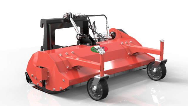
The Flail Mowers are designed for Category 1 - three point hitch or Quick-Hitch System mounting. These Fixed Bar Flail Mowers are ideal for ripping, leveling, finish grading, and backfilling applications at feedlots, outdoor arenas, building sites, and maintenance operations on farm and ranch lanes or roadways.
Using This Manual
Terminology
“Right” or “Left” as used in this manual is determined by facing the direction the machine will operate while in use unless otherwise stated.
Definitions
Note: A special point of information that the operator must be aware of before continuing.
Important: A special point of information related to its preceding topic. The intention is that this information should be read and noted before continuing.
Owner Assistance
The Warranty Registration card should be filled out by the dealer at the time of purchase. This information is necessary to provide you with quality customer service. If customer service or repair parts are required contact a dealer. A dealer has trained personnel, repair parts and equipment needed to service the machine.
The parts on your machine have been specially designed and should only be replaced with genuine parts.
Serial Number Plate
For prompt service always use the serial number and model number when ordering parts from your dealer. Be sure to include your serial and model numbers in correspondence also.
Thoroughly read and understand the instructions given in this manual before operation. Refer to the “Safety Decal”, read all instructions noted on them.
Do not allow anyone to operate this equipment who has not fully read and comprehended this manual and who has not been properly trained in the safe operation of the equipment.
Look For The Safety Alert Symbol
The SAFETY ALERT SYMBOL indicates there is a potential hazard to personal safety involved and extra safety precaution must be taken. When you see this symbol, be alert and carefully read the message that follows it. In addition to design and configuration of equipment, hazard control and accident prevention are dependent upon the awareness, concern, prudence and proper training of personnel involved in the operation, transport, maintenance and storage of equipment.
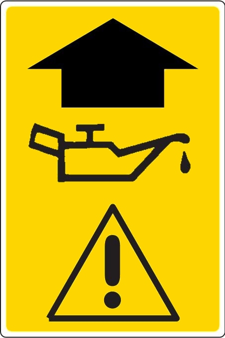
This booklet contains three "safety graphic symbols" which highlight the relevant danger levels or important information:
|
|
WARNING It draws the operator's attention to situations which can jeopardize people's safety. |
|
|
CAUTION It draws the attention to situations which jeopardize the machine efficiency but not people's safety. |
|
|
IMPORTANT It highlights general information which does not endanger people's safety or the efficiency of the parts.. |
For your protection
Thoroughly read and understand the “Safety Labels” section, read all instructions noted on them.
Shutdown and storage
Use safety lights and devices
Transport machinery safely
|
|
IMPORTANT Do not tow a load that is more than double the weight of tractor. |
Keep riders off machinery
Practice safe maintenance
Prepare for emergencies
Wear protective equipment
Avoid high pressure fluids hazard
Your Flail Mower comes equipped with all safety labels in place.
They were designed to help you safely operate your implement. Read and follow their directions.
To install new labels:
 |
 |
 |
 |
 |
Tractor Requirements
This hydraulic mower is designed for front use and equipped with a quick hitch hook. The oil flow should not exceed 45ltr/min and 160bar.
Assembly
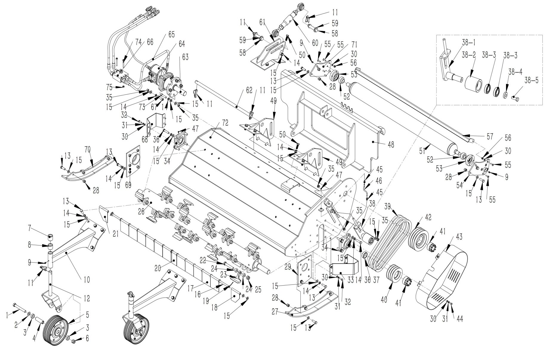
Refer to the parts illustration.
Tractor & wheel loader Hook-Up
Driveline Installation
|
|
CAUTION Tractor PTO shield and all mower guards must be in place at all times during operation! |
|
Model |
Working width |
Recommended power (hp) |
Oil (ltr) |
Category |
Weight |
Cutting blade |
|
WLF 1300 |
130 |
33 - 50 |
40 - 45 |
W. |
320 |
22 |
|
WLF 1700 |
170 |
33 - 50 |
40 - 45 |
W. |
353 |
28 |
Transporting
NOTE: Always disengage PTO before raising mower to transport position.
When traveling on public roads, whether at night or during the day, use accessory lights and devices for adequate warning to operators of other vehicles. Comply with all Federal, State, and local laws.
Mowing Instructions
Operating Instructions
Proper servicing and adjustments are the key to the long life of any machine. With careful and systematic
inspection of the mower, costly maintenance, time and repair can be avoided.
Before beginning to mow, the following inspection should be performed:
Leveling the Mower
NOTE: Tractor and mower should be on level ground.
Leveling can be adjusted at the tractor’s 3-point arms and center link.
Cutting Height Adjustment
The machines cutting height depends upon the position of the rear roller.
3-Point Hitch Adjustments
The 3-point hitch system on this mower has been designed for front to back flotation when mowing on uneven terrain. Adjust tractor’s top center link to place the upper hitch pin vertically above or slightly behind the lower hitch pins. The mower should be run with the back 15 degrees lower than the front.
The hitch can also be adjusted from side to side by turning the adjustment handle. Turn handle until you have achieved your desired location.
|
|
CAUTION Engage parking brake, shut off tractor, remove key and disengage PTO before making any height adjustments! |
Belt Tension
|
|
CAUTION Belt drive system under spring tension; use care to avoid bodily harm! |
The Belt tension should be checked after the first 20 hours of use. And then every 40 hours of use.
|
|
CAUTION Excessive tension on the belt may lead to premature failure of belt and drive components. Excessive tension on the belt may also lead to a safety hazard to the operator or bystanders. |
Maintenance
Proper servicing and adjustment is the key to the long life of any farm implement. With careful and systematic inspection, you can avoid costly maintenance, time and repair.
|
|
CAUTION For safety reasons, each maintenance operation must be performed with tractor PTO disengaged, mower lowered completely to ground and tractor engine shut off with ignition key removed. After using the mower for several hours, check all bolts to be sure they are tight and check drive belt tension.. |
Knife Replacement
|
|
IMPORTANT Make sure that the knife is the same length as the others on the mower. This will keep the rotor rotation balanced. |
V-Belt Installation
|
|
CAUTION Belt drive system under spring tension; use care to avoid bodily harm! |
Storage
At the end of the working season or when the mower will not be used for a long period, it is good practice to clean off any dirt or grease that may have accumulated on the mower and any of moving parts.
Lubrication
|
|
Type of Lubrication |
|
|
Driveline Shaft U-Joints |
|
Multi-purpose Grease |
|
Roller Bearing (Both Ends) |
||
|
Cutter Rotor Bearing (Both Ends) |
||
|
Gearbox |
Check oil level in gearbox by removing the plug located on the right hand side. Oil should be level with bottom of plug hole. Add oil if necessary by removing top fill plug and side plug. Add oil until it flows from side plug hole. Do not overfill! |
SAE 90W Gear Lube |
|
Driveline Profiles |
|
Multi-purpose Grease |
|
|
IMPORTANT Mower should be level when checking oil in gearbox! |
|
MODEL |
WLF1300 |
WLF1700 |
|
Structure weight |
320Kg |
353Kg |
|
Cutting width |
1300mm |
1700mm |
|
Hydraulic Flow |
42L/min-45Lmin, 180Bar |
42L/min-45L/min, 180Bar |
|
Hammer No. |
22pcs |
28 pcs |
|
Mounting Type |
Euro Hitch |
Euro Hitch |
|
Hydraulic Couples need |
3 line, oil-in, oil-out, drain port |
|
|
|
CAUTION Do not try to clean rear discharge area when mower is running. Bodily harm may occur! |
|
Problem |
Solution |
|
Belt slipping |
Unplug and clean mower deck. |
|
Remove belt guard shields and clean sheaves. |
|
|
Replace belt. |
|
|
Patches of uncut grass |
Mow at full throttle (540 PTO rpm), check PTO speed and tractor engine. |
|
Shift transmission to a lower gear. |
|
|
Tighten belts. |
|
|
Replace missing knives. |
|
|
Excessive vibration |
Replace knives. |
|
Replace drive belt. |
|
|
Replace pulleys or align. |
|
|
Remove belt guard shields & clean debris from belt area & sheaves. |
|
|
Gearbox noisy |
Check lubricant level. |
|
Knives scalping grass |
Raise cutting height by adjusting roller. |
|
Change mowing pattern. |
|
|
Reduce speed turns |
|
|
Uneven cut |
Shift to a lower gear. |
|
Level mower. |
|
|
Replace missing knives. |
|
|
Tractor loaded down by mower |
Mow at full throttle (540 PTO rpm). |
|
Shift to a lower gear. |
|
|
Clean mower. |
The tables shown below give correct torque values for various bolts and cap screws. Tighten all bolts to the torques specified unless otherwise noted. Check tightness of bolts periodically, using bolt torque chart as a guide. Replace hardware with the same strength bolt.
|
ENGLISH TORQUE SPECIFICATIONS |
||||||
|
|
SAE 2 |
SAE 5 |
SAE 8 |
|||
|
Bolt Diameter |
N.m |
lb-ft |
N.mt |
lb-ft |
N.m |
lb-ft |
|
1/4” |
8 |
6 |
12 |
9 |
17 |
12 |
|
5/16” |
13 |
10 |
25 |
19 |
36 |
27 |
|
3/8” |
27 |
20 |
45 |
33 |
63 |
45 |
|
7/16” |
41 |
30 |
72 |
53 |
100 |
75 |
|
1/2” |
61 |
45 |
110 |
80 |
155 |
115 |
|
9/16” |
95 |
60 |
155 |
115 |
200 |
165 |
|
5/8” |
128 |
95 |
215 |
160 |
305 |
220 |
|
3/4” |
225 |
165 |
390 |
290 |
540 |
400 |
|
7/8” |
230 |
170 |
570 |
420 |
880 |
650 |
|
METRIC TORQUE SPECIFICATIONS |
||||
|
|
8.8 |
10.9 |
||
|
Bolt Diameter |
N.m |
lb-ft |
N.m |
lb-ft |
|
M3 |
0.5 |
0.4 |
1.8 |
1.3 |
|
M4 |
3 |
2.2 |
4.5 |
3.3 |
|
M5 |
6 |
4 |
9 |
7 |
|
M6 |
10 |
7 |
15 |
11 |
|
M8 |
25 |
18 |
35 |
26 |
|
M10 |
50 |
37 |
70 |
52 |
|
M12 |
90 |
66 |
125 |
92 |
|
M14 |
140 |
103 |
200 |
148 |
|
M16 |
225 |
166 |
310 |
229 |
|
M20 |
435 |
321 |
610 |
450 |
|
M24 |
750 |
553 |
1050 |
744 |
|
M30 |
1495 |
1103 |
2100 |
1550 |
|
M36 |
2600 |
1917 |
3675 |
2710 |
Torque figures indicated above are valid for non-greased or non-oiled threads and heads otherwise specified. Therefore, do not grease or oil bolts or cap screws unless otherwise specified in this manual. When using locking elements, increase torque values by 5%.
|
WLF FLAIL MOWER ASSEMBLY |
|||
|---|---|---|---|
|
No. |
Part No. |
Description |
Quantity |
|
1 |
GB/T 5782 |
Bolt M16*120 |
2 |
|
2 |
GB/T 97.1 |
Washer 16 |
4 |
|
3 |
LM180.27 |
Bushing |
4 |
|
4 |
LM180.25 |
Bushing for wheel |
2 |
|
5 |
LM180.10 |
Wheel Φ220*75 |
2 |
|
6 |
GB/T 6182 |
Lock nut M16 |
2 |
|
7 |
WLF130.4 |
Adjust bushing 02 |
2 |
|
8 |
WLF130.3 |
Adjust bushing 01 |
2 |
|
9 |
JB / T 7940.1-1995 |
Grease nipple M8*1 |
4 |
|
10 |
WLF130.2 |
Wheel arm weldment |
2 |
|
No. |
Part No. |
Description |
Quantity |
|
11 |
DIN 11023 |
Lock pin Φ11*40 |
6 |
|
12 |
WLF130.1 |
Wheel fork weldment |
2 |
|
13 |
GB/T 70.1 |
Bolt M12*35 |
28 |
|
14 |
GB/T 93 |
Spring washer 12 |
42 |
|
15 |
GB/T 97.1 |
Washer 12 |
75 |
|
16 |
WLF130.6 |
Bar for fender |
1 |
|
17 |
EFGC175.24A |
Fender 95 |
11 |
|
18 |
EFGC175.24B |
Fender 95 |
1 |
|
19 |
GB/T 91 |
Cotter pin 3.2*22 |
2 |
|
20 |
EFGC175.24C |
Fender 24 |
1 |
|
No. |
Part No. |
Description |
Quantity |
|
21 |
EFGC175.24D |
Fender 95 |
1 |
|
22 |
GB/T 5785 |
Bolt M16*1.5*90 |
22 |
|
23 |
EF100.00.102B |
Hammer 350g |
22 |
|
24 |
EFGC175.28 |
Bushing for hammer seat |
44 |
|
25 |
GB/T 889.2 |
Locking nut M16*1.5 |
22 |
|
26 |
WLF130.13 |
Flail rotor weldment |
1 |
|
27 |
WLF130.8 |
Skid Left |
1 |
|
28 |
GB/T 6182 |
Locking nut M12 |
10 |
|
29 |
WLF130.12 |
Cover weldment Left |
1 |
|
30 |
GB/T 97.1 |
Washer 8 |
13 |
|
No. |
Part No. |
Description |
Quantity |
|
31 |
GB/T 93 |
Spring washer 8 |
11 |
|
32 |
GB/T 70.1 |
Bolt M8X25 |
8 |
|
33 |
WLF130.9 |
Protection plate 01 |
1 |
|
34 |
GB/T 7810 |
Bearing UCFU207 |
2 |
|
35 |
GB/T 6170 |
Nut M12 |
11 |
|
36 |
GB/T 70.1 |
Bolt M12*50 |
8 |
|
37 |
WLF130.26 |
Bushing |
1 |
|
No. |
Part No. |
Description |
Quantity |
|
38 |
WLF130.24 |
Tension roller assemble |
1 |
|
38-1 |
WLF130.24.1 |
Tension plate weldment |
1 |
|
38-2 |
WLF130.24-2 |
Tension Roller |
1 |
|
38-3 |
GB/T 276 |
Bearing 6005-Z |
2 |
|
38-4 |
WLF130.24-3 |
Washer |
1 |
|
38-5 |
GB/T 5783 |
Bolt M12*30 |
1 |
|
39 |
GB/T 11544 |
V-belt SPB1036 |
3 |
|
40 |
EFGC155.27 |
Small pulley |
1 |
|
No. |
Part No. |
Description |
Quantity |
|
41 |
JB/T 11544 |
Power Lock REACH 04 Type 35X60 |
2 |
|
42 |
EFGC155.31 |
Big pulley |
1 |
|
43 |
WLF130.23 |
Pulley cover |
1 |
|
44 |
GB/T 70.1 |
Bolt M8*16 |
3 |
|
45 |
M6X1-6X4 |
Lock nut connector |
2 |
|
46 |
WLF130.25 |
Pipe for grease Φ6*Φ4 |
1 |
|
47 |
JB/T 7940.1 |
Grease nipple M6*1 |
2 |
|
48 |
WLFEH.0 |
Mount connector euro hitch |
1 |
|
49 |
WLF130.29 |
Low linkage weldment |
2 |
|
50 |
GB/T 70.1 |
Bolt M12*35 |
8 |
|
No. |
Part No. |
Description |
Quantity |
|
51 |
WLF130.16 |
Rear Roller |
1 |
|
52 |
UC205 |
Bearing UC205 |
2 |
|
53 |
EFGC175.19 |
Bearing seat |
2 |
|
54 |
WLF130.145 |
Left connection plate for roller |
1 |
|
55 |
GB/T 70.3 |
Nut bolt M8*25 |
10 |
|
56 |
GB/T 6182 |
Nut M8 |
2 |
|
57 |
WLF130.17 |
Scriper |
1 |
|
58 |
WLF130.22 |
Pin for top linkage |
2 |
|
59 |
GB/T 97.1 |
Washer 16 |
3 |
|
60 |
WLF130.19 |
Adjust link rod |
1 |
|
No. |
Part No. |
Description |
Quasntity |
|
61 |
WLF130.18 |
Top linkage weldment |
1 |
|
62 |
WLF130.21 |
Pin for down linkage |
1 |
|
63 |
WLF130.30 |
Shaft coupling |
1 |
|
64 |
CM-WLF |
Gear motor |
1 |
|
65 |
WLF130.27 |
Oil pipe assembling |
1 |
|
66 |
WLF130.28 |
Checking valve and priority valve |
1 |
|
67 |
GB/T 70.1 |
Head screw M12*50 |
4 |
|
68 |
WLF130.10 |
Protection plate 02 |
1 |
|
No. |
Part No. |
Description |
Quantity |
|
69 |
WLF130.11 |
Cover weldment Right |
1 |
|
70 |
WLF130.7 |
Skids Right |
1 |
|
71 |
WLF130.14 |
Right connection plate for roller |
1 |
|
72 |
WLF130.5 |
Mower deck weldment |
1 |
|
73 |
GB/T 70.1 |
Head screw M12*45 |
4 |
|
74 |
GB/T 70.1 |
Bolt M8*60 |
2 |
|
75 |
GB/T 6170 |
Nut M8 |
2 |
|
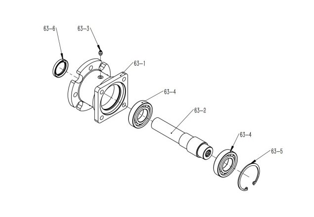
WLF130.30 SHAFT COUPLE |
|||
|
No. |
Part No. |
Description |
Quantity |
|
63-1 |
LM180.17-1 |
Deck |
1 |
|
63-2 |
WLF130.30-1 |
Shaft |
1 |
|
63-3 |
JB / T 7940.1-1995 |
Grease nipple M8*1 |
1 |
|
63-4 |
GB/T 276 |
Bearing 6208-Z |
2 |
|
63-5 |
GB/T 893.1 |
Circlip 80 |
1 |
|
63-6 |
GB/T 1387.1 |
Oil seal FB type 40*55*8 |
1 |
|
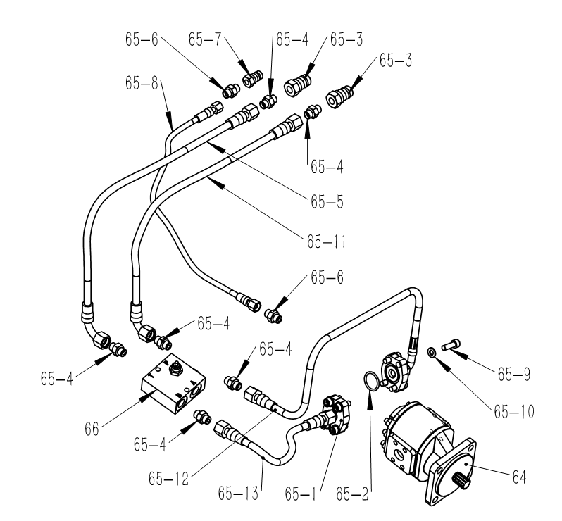
WLF130.27 OIL PIPE ASSEMBLING |
|||
|
No. |
Part No. |
Description |
Quantity |
|---|---|---|---|
|
65-1 |
LM180.26-1 |
Couple |
2 |
|
65-2 |
AS 568 |
O-seal 219 Φ32.92*3.53 |
2 |
|
65-3 |
GB/T 5862 |
Quick couple G1/2 |
2 |
|
65-4 |
GE15LRED |
Connector |
6 |
|
65-5 |
WLF130.27-1 |
Oil pipe 01 |
1 |
|
65-6 |
GE10SRED |
Connector |
2 |
|
65-7 |
GB/T 5862 |
Quick couple G3/8 |
1 |
|
65-8 |
WLF130.27-2 |
Oil pipe 02 |
1 |
|
65-9 |
GB/T 70.1 |
Head screw M10*30 |
8 |
|
65-10 |
GB/T 97.1 |
Washer 10 |
8 |
|
65-11 |
WLF130.27-3 |
Oil pipe 03 |
1 |
|
65-12 |
WLF130.27-4 |
Oil pipe 04 |
1 |
|
65-13 |
WLF130.27-5 |
Oil pipe 05 |
1 |