
WARNING
Before operating the Flail mower, read the following safety instructions. Failure to comply with these warnings may result in serious injury or death.
|
|
WARNING Before operating the Flail mower, read the following safety instructions. Failure to comply with these warnings may result in serious injury or death. |
YOU are responsible for the SAFE operation and maintenance of your Flail mower. YOU must ensure that you and anyone else who is going to operate, maintain or work around the Flail mower is familiar with the operating and maintenance procedures and related SAFETY information contained in this manual. This manual will take you step- by-step through your working day and alert you to all good safety practices that should be adhered to while operating the Flail mower.
Remember, YOU are the key to safety. Good safety practices not only protect you but also the people around you. Make these practices a working part of your safety program. Be certain that EVERYONE operating this equipment is familiar with the recommended operating and maintenance procedures and follows all the safety precautions. Most accidents can be prevented. Do not risk injury of death by ignoring good safety practices.

|

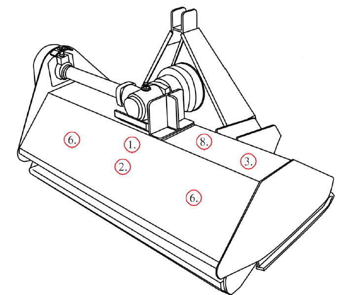
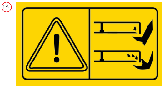
The position of safety decals is shown in the illustrations below. Good safety requires that you familiarize yourself with the various safety signs, and increase your SAFETY AWARENESS.

 |
 |
 |
 |
 |
 |
 |
 |
 |
 |
 |
|
Model |
EF-95 |
EF-115 |
EF-135 |
EF-175 |
|
Tractor (HP) |
12-25 |
18-25 |
25-30 |
30-40 |
|
3.P.L |
Cat-1 |
Cat-1 |
Cat-1 |
Cat-1 |
|
Length |
1065 |
1265 |
1485 |
1885 |
|
Width |
790 |
790 |
790 |
790 |
|
Height |
845 |
845 |
845 |
845 |
|
Weight (kg) |
145 |
180 |
215 |
275 |
|
Cutting Width |
950 |
1115 |
1315 |
1715 |
|
PTO (r/min) |
540 |
540 |
540 |
540 |
|
Gear Box (HP) |
30 |
50 |
50 |
50 |
|
|
15 |
20 |
24 |
28 |
|
|
30 |
40 |
48 |
56 |
USES
FEATURES
An Identification plate is affixed to the frame of each implement. It contains the “CE” Certification brand and information about: the Manufacturer, Type, Serial Number, Weight and Year of Manufacture.
CE Identification Plate

Before operating the machine, the following areas should be checked off:
Adjusting the height
To get the most out of your flail mower, it should be set within the recommended height.
To save fuel and power, and reduce wear and tear, the cutting height must be regulated correctly.
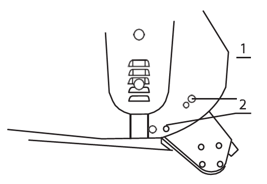
When adjusting the working height, loosen screw (1), remove screw (2) on both sides; The roller height (see drawing) can be adjusted by aligning the selected hole in the roller support bracket at position 2. The lowest hole is the highest working height; put the screw (2) into the selected hole; tighten screw (1) and screw (2).
Flail mower adjustment
When the Flail mower has been set up with the required tolerances: operate the Flail mower with tractor in low range and the PTO delivering 540 RPM.


Approx 10 mm deflection
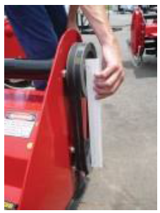
Align with a straight edge
Before starting the machine, check and adjust the following items:
Storage Position
Operating Position
In order to keep the machine stable, lower the adjustment stand when the machine is stopped (see above drawing). Follow all safety precautions detailed in this manual.
The machine is equipped with a standard category one, three point linkage.
Back the tractor into position in front of the flail mower Lower the tractor hydraulic lift arms. Turn the tractor off. Maneuver the implement by hand and attach the lower link arms to the lower link pin. Ensure they are secured with lynch pin. Attach the top link to the top link bracket. Adjust the lower link sway chains to allow minimal lateral movement. Attach the PTO shaft to the tractor PTO ensuring it has been cut to the required length.
Each 4 hours of work
After 50 hours of work
Check and fill the gearbox to the required level, using oil type SAE 90 EP API GL4.
Each 100 hours of work
Check the gearbox oil level. Replace as required.
Fluids and lubricants
Grease: Use multi-purpose lithium based grease.
Gear Box Oil: Use SAE 90 Gear oil.
Storing Lubricants: Your machine can operate at top efficiency only if clean lubricants are used. Use clean containers to handle all lubricants. Store them in an area protected from dust, moisture and other contaminants.
Greasing
The period recommended is based on normal operating conditions. Severe or unusual conditions may require more frequent maintenance.
|
|
NOTE The operator should put on gloves and use suitable tools before changing blade.. |
8 hours or daily maintenance
Season maintenance
Annual maintenance
Gear box maintenance
The oil should be drained out and replaced after the first 50 hours of operation. Then the oil should be changed every 250 hours, or at least once a year.
Drain oil from the gearbox thoroughly. Check and clean it. Fill with new gear oil up to the dedicated oil level.
The draining procedure is as follows: remove the draining bolt under the gear box, so that the oil drains off. After the oil is drained out, put the plug back and fill with gear oil up to the dedicated oil level.
|
|
8hrs/Daily |
50hrs/Weekly |
Annually |
|
Lubricate PTO Shaft |
x |
x |
x |
|
Lubricate caster wheels |
x |
x |
x |
|
Lubricate blade spindle |
x |
x |
x |
|
Check gear box oil level |
|
x |
x |
|
Clean machine |
|
|
x |
|
Lubricate and clean PTO shaft cover |
|
|
x |
PTO shaft maintenance
The PTO shaft is designed to telescope to allow for dimensional changes as the machine goes through its operating range. A tubular guard encloses the driving components and is designed to turn relative to the driving components. The shaft should telescope easily and the guard turn freely on the shaft at all times. Annual disassembly, cleaning and lubrication is recommended to insure that all components function as intended. To maintain the shaft, follow this procedure:
Oil level
|
|
NOTE Check the oil level only when the unit is cold and the machine is on the level. |
Before the machine is started up, check the following items regularly:
|
FAILURE |
CAUSE |
SOLUTION |
LEVEL OF DANGER |
|
Excessive vibration of the machine |
Broken flails |
Replace broken flails |
Flails can be replaced by a competent operator. In the other cases, replacement must be done by specialised staff. |
|
Broken rotor support |
Replace rotor support with original parts |
||
|
Broken driving support shaft |
Replace shaft support with original parts |
||
|
The worst: bent rotor |
Replace rotor with original parts |
||
|
The grass is not cut |
Broken flails |
Replace flails |
For replacement of flails, adjustment or replacement belts and fixing lock joints, see paragraph relating to maintenance. |
|
Belt slipping |
Adjust belt tension |
||
|
Broken belts |
Replace belts |
||
|
Pulleys slipping on shafts |
Fix pulley lock joints |
||
|
Broken gear box |
Repairing or replacement of gear box |
||
|
Clogging of hammers/ knives |
Rotor speed is too low |
Increase rotor speed |
|
|
Excessive wear of hammers/knives |
Rotor speed is too high |
Decrease rotor speed |
|
|
Flail mower vibrates during works |
Foreign matter stuck in between blades |
Remove foreign matter |
Secure flail mower on a mechanical stand before maintaining blades or rotor. |
|
Hammers/knives broken |
Replace hammer/knives |
||
|
Bolts of the rotor shaft support have come loose |
Lock bolts |

|
No. |
Part No. |
Name & Specifications |
QTY |
|||||
|
EFGC-105 |
EFGC-125 |
EFGC-135 |
EFGC-145 |
EFGC-155 |
EFGC-175 |
|||
|
1 |
|
|
|
|
|
|
Blade axle subassembly |
1 |
|
2 |
EF100.00.122 |
EF100.00.122 |
EF100.00.122 |
EF100.00.122 |
EF100.00.122 |
EF100.00.122 |
Fender |
13 |
|
3 |
EF100.00.121 |
EF100.00.121 |
EF100.00.121 |
EF100.00.121 |
EF100.00.121 |
EF100.00.121 |
Fender |
1 |
|
4 |
GB5783-86 |
GB5783-86 |
GB5783-86 |
GB5783-86 |
GB5783-86 |
GB5783-86 |
Bolt M12x30 |
23 |
|
5 |
GB97.1-85 |
GB97.1-85 |
GB97.1-85 |
GB97.1-85 |
GB97.1-85 |
GB97.1-85 |
Plain washer 12 |
40 |
|
6 |
EFGC100.012 |
EFGC120.012 |
EFGC130.012 |
EFGC140.012 |
EFGC150.012 |
EFGC170.012 |
Hanging weldment |
2 |
|
7 |
EF100.00.106 |
EF100.00.106 |
EF100.00.106 |
EF100.00.106 |
EF100.00.106 |
EF100.00.106 |
Spacer |
2 |
|
8 |
EF100.00.014 |
EF100.00.014 |
EF100.00.014 |
EF100.00.014 |
EF100.00.014 |
EF100.00.014 |
Pin shaft weldment |
2 |
|
9 |
GB6184-86 |
GB6184-86 |
GB6184-86 |
GB6184-86 |
GB6184-86 |
GB6184-86 |
Locking nut M12 |
44 |
|
10 |
GB5783-86 |
GB5783-86 |
GB5783-86 |
GB5783-86 |
GB5783-86 |
GB5783-86 |
Bolt M12x40 |
8 |
|
No. |
EFGC-105 |
EFGC-125 |
EFGC-135 |
EFGC-145 |
EFGC-155 |
EFGC-175 |
Name & Specifications |
QTY |
|
11 |
EFGC100.101 |
EFGC120.101 |
EFGC130.101 |
EFGC140.101 |
EFGC150.101 |
EFGC170.101 |
Splint |
4 |
|
12 |
EF100.00.016 |
EF100.00.016 |
EF100.00.016 |
EF100.00.016 |
EF100.00.016 |
EF100.00.016 |
Suspension plate (L) |
1 |
|
13 |
EF100.00.017 |
EF100.00.017 |
EF100.00.017 |
EF100.00.017 |
EF100.00.017 |
EF100.00.017 |
Hook |
1 |
|
14 |
EF100.00.105 |
EF100.00.105 |
EF100.00.105 |
EF100.00.105 |
EF100.00.105 |
EF100.00.105 |
Clamp for hook |
2 |
|
15 |
EF100.00.107 |
EF100.00.107 |
EF100.00.107 |
EF100.00.107 |
EF100.00.107 |
EF100.00.107 |
Fixing plate |
1 |
|
16 |
GB5783-86 |
GB5783-86 |
GB5783-86 |
GB5783-86 |
GB5783-86 |
GB5783-86 |
Bolt M12x35 |
5 |
|
17 |
|
|
|
|
|
|
R pin |
1 |
|
18 |
EF100.00.117 |
EF100.00.117 |
EF100.00.117 |
EF100.00.117 |
EF100.00.117 |
EF100.00.117 |
Cover |
1 |
|
19 |
EF100.00.027 |
EF100.00.027 |
EF100.00.027 |
EF100.00.027 |
EF100.00.027 |
EF100.00.027 |
Supporting frame |
1 |
|
20 |
EF100.00.111 |
EF100.00.111 |
EF100.00.111 |
EF100.00.111 |
EF100.00.111 |
EF100.00.111 |
Bent pin |
1 |
|
No. |
EFGC-105 |
EFGC-125 |
EFGC-135 |
EFGC-145 |
EFGC-155 |
EFGC-175 |
Name & Specifications |
QTY |
|
21 |
EF100.00.020 |
EF100.00.020 |
EF100.00.020 |
EF100.00.020 |
EF100.00.020 |
EF100.00.020 |
Suspension plate (R) |
1 |
|
22 |
EF100.00.018 |
EF100.00.018 |
EF100.00.018 |
EF100.00.018 |
EF100.00.018 |
EF100.00.018 |
Bracket weldment |
1 |
|
23 |
EF100.00.019 |
EF100.00.019 |
EF100.00.019 |
EF100.00.019 |
EF100.00.019 |
EF100.00.019 |
Pin shaft weldment |
1 |
|
24 |
EFGC100.013 |
EFGC120.013 |
EFGC130.013 |
EFGC140.013 |
EFGC150.013 |
EFGC170.013 |
Base plate (L) |
1 |
|
25 |
EFG120.102 |
EFG120.102 |
EFG120.102 |
EFG120.102 |
EFG120.102 |
EFG120.102 |
Supporting for roller (L) |
1 |
|
26 |
EF100.00.112 |
EF100.00.112 |
EF100.00.112 |
EF100.00.112 |
EF100.00.112 |
EF100.00.112 |
Guard shade |
1 |
|
27 |
GB96-85 |
GB96-85 |
GB96-85 |
GB96-85 |
GB96-85 |
GB96-85 |
Plain washer 10 |
4 |
|
28 |
GB93-87 |
GB93-87 |
GB93-87 |
GB93-87 |
GB93-87 |
GB93-87 |
Spring washer 10 |
4 |
|
29 |
GB5783-86 |
GB5783-86 |
GB5783-86 |
GB5783-86 |
GB5783-86 |
GB5783-86 |
Bolt M10x25 |
4 |
|
30 |
GB6173-86 |
GB6173-86 |
GB6173-86 |
GB6173-86 |
GB6173-86 |
GB6173-86 |
Nut M16x1.5 |
1 |
|
No. |
EFGC-105 |
EFGC-125 |
EFGC-135 |
EFGC-145 |
EFGC-155 |
EFGC-175 |
Name & Specifications |
QTY |
|
31 |
GB5786-86 |
GB5786-86 |
GB5786-86 |
GB5786-86 |
GB5786-86 |
GB5786-86 |
Bolt M16x1.5x50 |
1 |
|
32 |
EF100.00.012 |
EF100.00.012 |
EF100.00.012 |
EF100.00.012 |
EF100.00.012 |
EF100.00.012 |
Bearing with flange UC205 |
2 |
|
33 |
EFGC100.015 |
EFGC120.015 |
EFGC130.015 |
EFGC140.015 |
EFGC150.015 |
EFGC170.015 |
Gear box assembly |
1 |
|
34 |
EF100.00.024 |
EF120.00.024 |
EF130.00.024 |
EF140.00.024 |
EF150.00.024 |
EF170.00.024 |
Mud shield |
1 |
|
35 |
GB6184-86 |
GB6184-86 |
GB6184-86 |
GB6184-86 |
GB6184-86 |
GB6184-86 |
Locking nut M14 |
2 |
|
36 |
GB97.1-85 |
GB97.1-85 |
GB97.1-85 |
GB97.1-85 |
GB97.1-85 |
GB97.1-85 |
Plain washer 14 |
2 |
|
37 |
EFGC120.102 |
EFGC120.102 |
EFGC120.102 |
EFGC120.102 |
EFGC120.102 |
EFGC120.102 |
Tension plate |
1 |
|
38 |
GB5783-86 |
GB5783-86 |
GB5783-86 |
GB5783-86 |
GB5783-86 |
GB5783-86 |
Bolt M14x35 |
2 |
|
39 |
GB6184-86 |
GB6184-86 |
GB6184-86 |
GB6184-86 |
GB6184-86 |
GB6184-86 |
Locking nut M8 |
2 |
|
40 |
GB2673-86 |
GB2673-86 |
GB2673-86 |
GB2673-86 |
GB2673-86 |
GB2673-86 |
Hex.head bolt M8x25 |
10 |
|
No. |
EFGC-105 |
EFGC-125 |
EFGC-135 |
EFGC-145 |
EFGC-155 |
EFGC-175 |
Name & Specifications |
QTY |
|
41 |
EFG100.012 |
EFG120.012 |
EFG130.012 |
EFG140.012 |
EFG150.012 |
EFG170.012 |
Roller weldment |
1 |
|
42 |
GB1152-89 |
GB1152-89 |
GB1152-89 |
GB1152-89 |
GB1152-89 |
GB1152-89 |
Oil cup M6 |
2 |
|
43 |
EFG120.101 |
EFG120.101 |
EFG120.101 |
EFG120.101 |
EFG120.101 |
EFG120.101 |
Supporting for roller (R) |
1 |
|
44 |
EFGC120.016 |
EFGC120.016 |
EFGC120.016 |
EFGC120.016 |
EFGC120.016 |
EFGC120.016 |
Belt cover |
1 |
|
45 |
JB/T7934Z3 |
JB/T7934Z3 |
JB/T7934Z3 |
JB/T7934Z3 |
JB/T7934Z3 |
JB/T7934Z3 |
Swellable sleeve |
2 |
|
46 |
GB5782-86 |
GB5782-86 |
GB5782-86 |
GB5782-86 |
GB5782-86 |
GB5782-86 |
Bolt M12x80 |
1 |
|
47 |
GB96-85 |
GB96-85 |
GB96-85 |
GB96-85 |
GB96-85 |
GB96-85 |
Plain washer 12 |
5 |
|
48 |
GB-T1154-97 |
GB-T1154-97 |
GB-T1154-97 |
GB-T1154-97 |
GB-T1154-97 |
GB-T1154-97 |
Strap A965 |
2 |
|
49 |
RK120.113 |
RK120.113 |
RK120.113 |
RK120.113 |
RK120.113 |
RK120.113 |
Big belt pulley |
1 |
|
50 |
RK120.110 |
RK120.110 |
RK120.110 |
RK120.110 |
RK120.110 |
RK120.110 |
Small belt pulley |
1 |
|
No. |
EFGC-105 |
EFGC-125 |
EFGC-135 |
EFGC-145 |
EFGC-155 |
EFGC-175 |
Name & Specifications |
QTY |
|
51 |
EFGC100.014 |
EFGC120.014 |
EFGC130.014 |
EFGC140.014 |
EFGC150.014 |
EFGC170.014 |
Base plate (R) |
1 |
|
52 |
EFGC100.011 |
EFGC120.011 |
EFGC130.011 |
EFGC140.011 |
EFGC150.011 |
EFGC170.011 |
The cover weldment |
1 |
|
53 |
GB1152-89 |
GB1152-89 |
GB1152-89 |
GB1152-89 |
GB1152-89 |
GB1152-89 |
Oil cup M8x1 |
2 |
|
54 |
GB93-87 |
GB93-87 |
GB93-87 |
GB93-87 |
GB93-87 |
GB93-87 |
Spring washer 12 |
12 |
|
55 |
GB97.1-85 |
GB97.1-85 |
GB97.1-85 |
GB97.1-85 |
GB97.1-85 |
GB97.1-85 |
Plain washer 10 |
18 |
|
56 |
GB879-86 |
GB879-86 |
GB879-86 |
GB879-86 |
GB879-86 |
GB879-86 |
Elastic cylindrical pin 4x22 |
2 |
|
57 |
EF100.00.123 |
EF120.00.123 |
EF130.00.123 |
EF140.00.123 |
EF150.00.123 |
EF170.00.123 |
Shaft for fender |
1 |

|
No. |
Part No. |
Name & Specifications |
QTY |
|||||
|
EFGC-105 |
EFGC-125 |
EFGC-135 |
EFGC-145 |
EFGC-155 |
EFGC-175 |
|||
|
1 |
UC207-Z |
UC207-Z |
UC207-Z |
UC207-Z |
UC207-Z |
UC207-Z |
Bearing with flange 90207 |
2 |
|
2 |
EFGC100.013 |
EFGC120.013 |
EFGC130.013 |
EFGC140.013 |
EFGC150.013 |
EFGC170.013 |
Blade axle weldment |
1 |
|
3 |
GB5782-86 |
GB5782-86 |
GB5782-86 |
GB5782-86 |
GB5782-86 |
GB5782-86 |
Bolt M12x80 |
20 |
|
4 |
EF100.00.101 |
EF100.00.101 |
EF100.00.101 |
EF100.00.101 |
EF100.00.101 |
EF100.00.101 |
Sleeve |
40 |
|
5 |
EF100.00.102 |
EF100.00.102 |
EF100.00.102 |
EF100.00.102 |
EF100.00.102 |
EF100.00.102 |
Blade |
40 |
|
6 |
GB6184-86 |
GB6184-86 |
GB6184-86 |
GB6184-86 |
GB6184-86 |
GB6184-86 |
Locking nut M12 |
20 |
|
7 |
GB13871-94 |
GB13871-94 |
GB13871-94 |
GB13871-94 |
GB13871-94 |
GB13871-94 |
Oil seal FB55x80x8 |
1 |
|
8 |
RK120.109 |
RK120.109 |
RK120.109 |
RK120.109 |
RK120.109 |
RK120.109 |
Oil-sealing sleeve |
1 |
|
No. |
Part No. |
Name & Specifications |
QTY |
|||||
|
EFGC-105 |
EFGC-125 |
EFGC-135 |
EFGC-145 |
EFGC-155 |
EFGC-175 |
|||
|
1 |
GB13871-94 |
GB13871-94 |
GB13871-94 |
GB13871-94 |
GB13871-94 |
GB13871-94 |
Oil seal 35×62×10 |
1 |
|
2 |
GB893.1-86 |
GB893.1-86 |
GB893.1-86 |
GB893.1-86 |
GB893.1-86 |
GB893.1-86 |
Circlip 62 |
1 |
|
3 |
GB/T276-94 |
GB/T276-94 |
GB/T276-94 |
GB/T276-94 |
GB/T276-94 |
GB/T276-94 |
Bearing 6007 |
1 |
|
4 |
EFGC100.133 |
EFGC120.133 |
EFGC130.133 |
EFGC140.133 |
EFGC150.133 |
EFGC170.133 |
Shaft |
1 |
|
5 |
GB1096-79 |
GB1096-79 |
GB1096-79 |
GB1096-79 |
GB1096-79 |
GB1096-79 |
Key A10x40 |
1 |
|
6 |
EFGC120.132 |
EFGC120.132 |
EFGC120.132 |
EFGC120.132 |
EFGC120.132 |
EFGC120.132 |
Connected sleeve |
1 |
|
7 |
EFGC120.131 |
EFGC120.131 |
EFGC120.131 |
EFGC120.131 |
EFGC120.131 |
EFGC120.131 |
Paper gasket |
1 |
|
No. |
EFGC-105 |
EFGC-125 |
EFGC-135 |
EFGC-145 |
EFGC-155 |
EFGC-175 |
Name & Specifications |
QTY |
|
8 |
GB1096-79 |
GB1096-79 |
GB1096-79 |
GB1096-79 |
GB1096-79 |
GB1096-79 |
Key A10x70 |
1 |
|
9 |
XH50.300Z.02 |
XH50.300Z.02 |
XH50.300Z.02 |
XH50.300Z.02 |
XH50.300Z.02 |
XH50.300Z.02 |
Gearbox assembly |
1 |
|
10 |
EFGC100.018 |
EFGC120.018 |
EFGC130.018 |
EFGC140.018 |
EFGC150.018 |
EFGC170.018 |
Shaft tube weldment |
1 |
|
11 |
ZBT 32001.3-87 |
ZBT 32001.3-87 |
ZBT 32001.3-87 |
ZBT 32001.3-87 |
ZBT 32001.3-87 |
ZBT 32001.3-87 |
Retainer |
2 |
|
12 |
GB93-87 |
GB93-87 |
GB93-87 |
GB93-87 |
GB93-87 |
GB93-87 |
Plain washer 12 |
4 |
|
13 |
GB5783-86 |
GB5783-86 |
GB5783-86 |
GB5783-86 |
GB5783-86 |
GB5783-86 |
Hex. head bolt M12x35 |
4 |
|
No. |
Part No. |
Name & Specifications |
QTY |
|||||
|
EFGCH-105 |
EFGCH-125 |
EFGCH-135 |
EFGCH-145 |
EFGCH-155 |
EFGCH-175 |
|||
|
1 |
EF100.00.122 |
EF100.00.122 |
EF100.00.122 |
EF100.00.122 |
EF100.00.122 |
EF100.00.122 |
Fender |
13 |
|
2 |
EF100.00.121 |
EF100.00.121 |
EF100.00.121 |
EF100.00.121 |
EF100.00.121 |
EF100.00.121 |
Fender |
1 |
|
3 |
EF100.00.123 |
EF120.00.123 |
EF130.00.123 |
EF140.00.123 |
EF150.00.123 |
EF170.00.123 |
Shaft for fender |
1 |
|
4 |
GB879-86 |
GB879-86 |
GB879-86 |
GB879-86 |
GB879-86 |
GB879-86 |
Elastic cylindrical pin 4x22 |
2 |
|
5 |
GB97.1-85 |
GB97.1-85 |
GB97.1-85 |
GB97.1-85 |
GB97.1-85 |
GB97.1-85 |
Plain washer 10 |
18 |
|
6 |
FMR120.105 |
FMR120.105 |
FMR120.105 |
FMR120.105 |
FMR120.105 |
FMR120.105 |
Lockpin plate |
2 |
|
7 |
FMR120.104 |
FMR120.104 |
FMR120.104 |
FMR120.104 |
FMR120.104 |
FMR120.104 |
Pin for lifting (D) |
2 |
|
8 |
200.56.011-1 |
200.56.011-1 |
200.56.011-1 |
200.56.011-1 |
200.56.011-1 |
200.56.011-1 |
Lockpin |
2 |
|
9 |
EFGCH120.018 |
EFGCH120.018 |
EFGCH120.018 |
EFGCH120.018 |
EFGCH120.018 |
EFGCH120.018 |
Connecting bracket (L) |
1 |
|
10 |
EFGC120.101 |
EFGC120.101 |
EFGC120.101 |
EFGC120.101 |
EFGC120.101 |
EFGC120.101 |
Splint |
7 |
|
No. |
EFGCH-105 |
EFGCH-125 |
EFGCH-135 |
EFGCH-145 |
EFGCH-155 |
EFGCH-175 |
Name & Specifications |
QTY |
|
11 |
GB6184-86 |
GB6184-86 |
GB6184-86 |
GB6184-86 |
GB6184-86 |
GB6184-86 |
Locking nut M10 |
4 |
|
12 |
GB5783-86 |
GB5783-86 |
GB5783-86 |
GB5783-86 |
GB5783-86 |
GB5783-86 |
Bolt M10x70 |
4 |
|
13 |
GB97.1-85 |
GB97.1-85 |
GB97.1-85 |
GB97.1-85 |
GB97.1-85 |
GB97.1-85 |
Plain washer 12 |
53 |
|
14 |
GB6184-86 |
GB6184-86 |
GB6184-86 |
GB6184-86 |
GB6184-86 |
GB6184-86 |
Locking nut M12 |
50 |
|
15 |
|
|
R pin |
|
|
1 |
|
|
|
16 |
EF100.00.027 |
EF100.00.027 |
EF100.00.027 |
EF100.00.027 |
EF100.00.027 |
EF100.00.027 |
Supporting frame |
1 |
|
17 |
EF100.00.111 |
EF100.00.111 |
EF100.00.111 |
EF100.00.111 |
EF100.00.111 |
EF100.00.111 |
Bent pin |
1 |
|
18 |
EF100.00.117 |
EF100.00.117 |
EF100.00.117 |
EF100.00.117 |
EF100.00.117 |
EF100.00.117 |
Cover |
1 |
|
19 |
EF100.00.019 |
EF100.00.019 |
EF100.00.019 |
EF100.00.019 |
EF100.00.019 |
EF100.00.019 |
Pin shaft weldment |
1 |
|
20 |
EFGCH120.016 |
EFGCH120.016 |
EFGCH120.016 |
EFGCH120.016 |
EFGCH120.016 |
EFGCH120.016 |
Hanging weldment |
1 |
|
No. |
EFGCH-105 |
EFGCH-125 |
EFGCH-135 |
EFGCH-145 |
EFGCH-155 |
EFGCH-175 |
Name & Specifications |
QTY |
|
21 |
GB5783-86 |
GB5783-86 |
GB5783-86 |
GB5783-86 |
GB5783-86 |
GB5783-86 |
Bolt M10x25 |
4 |
|
22 |
GB93-87 |
GB93-87 |
GB93-87 |
GB93-87 |
GB93-87 |
GB93-87 |
Spring washer 12 |
4 |
|
23 |
GB96-85 |
GB96-85 |
GB96-85 |
GB96-85 |
GB96-85 |
GB96-85 |
Plain washer 10 |
4 |
|
24 |
EF100.00.112 |
EF100.00.112 |
EF100.00.112 |
EF100.00.112 |
EF100.00.112 |
EF100.00.112 |
Guard shade |
1 |
|
25 |
EFGC100.011 |
EFGC120.011 |
EFGC130.011 |
EFGC140.011 |
EFGC150.011 |
EFGC170.011 |
The cover weldment |
1 |
|
26 |
EFGC100.015 |
EFGC120.015 |
EFGC130.015 |
EFGC140.015 |
EFGC150.015 |
EFGC170.015 |
Gear box assembly |
1 |
|
27 |
GB6184-86 |
GB6184-86 |
GB6184-86 |
GB6184-86 |
GB6184-86 |
GB6184-86 |
Locking nut M14 |
2 |
|
28 |
GB97.1-85 |
GB97.1-85 |
GB97.1-85 |
GB97.1-85 |
GB97.1-85 |
GB97.1-85 |
Plain washer 14 |
2 |
|
29 |
EFGC120.102 |
EFGC120.102 |
EFGC120.102 |
EFGC120.102 |
EFGC120.102 |
EFGC120.102 |
Tension plate |
1 |
|
30 |
GB5786-86 |
GB5786-86 |
GB5786-86 |
GB5786-86 |
GB5786-86 |
GB5786-86 |
Bolt M16x1.5x50 |
1 |
|
No. |
EFGCH-105 |
EFGCH-125 |
EFGCH-135 |
EFGCH-145 |
EFGCH-155 |
EFGCH-175 |
Name & Specifications |
QTY |
|
31 |
GB6173-86 |
GB6173-86 |
GB6173-86 |
GB6173-86 |
GB6173-86 |
GB6173-86 |
Nut M16x1.5 |
1 |
|
32 |
GB5783-86 |
GB5783-86 |
GB5783-86 |
GB5783-86 |
GB5783-86 |
GB5783-86 |
Bolt M14x35 |
2 |
|
33 |
EFG100.012 |
EFG120.012 |
EFG130.012 |
EFG140.012 |
EFG150.012 |
EFG170.012 |
Roller weldment |
1 |
|
34 |
EF100.00.024 |
EF120.00.024 |
EF130.00.024 |
EF140.00.024 |
EF150.00.024 |
EF170.00.024 |
Mud shield |
1 |
|
35 |
GB1152-89 |
GB1152-89 |
GB1152-89 |
GB1152-89 |
GB1152-89 |
GB1152-89 |
Oil cup M6 |
2 |
|
36 |
GB6184-86 |
GB6184-86 |
GB6184-86 |
GB6184-86 |
GB6184-86 |
GB6184-86 |
Locking nut M8 |
2 |
|
37 |
GB2673-86 |
GB2673-86 |
GB2673-86 |
GB2673-86 |
GB2673-86 |
GB2673-86 |
Hex.head bolt M8x25 |
10 |
|
38 |
EF100.00.012 |
EF100.00.012 |
EF100.00.012 |
EF100.00.012 |
EF100.00.012 |
EF100.00.012 |
Bearing with flange UC205 |
2 |
|
39 |
EFGC120.016 |
EFGC120.016 |
EFGC120.016 |
EFGC120.016 |
EFGC120.016 |
EFGC120.016 |
Belt cover |
1 |
|
40 |
GB96-85 |
GB96-85 |
GB96-85 |
GB96-85 |
GB96-85 |
GB96-85 |
Plain washer 12 |
5 |
|
No. |
EFGCH-105 |
EFGCH-125 |
EFGCH-135 |
EFGCH-145 |
EFGCH-155 |
EFGCH-175 |
Name & Specifications |
QTY |
|
41 |
GB5782-86 |
GB5782-86 |
GB5782-86 |
GB5782-86 |
GB5782-86 |
GB5782-86 |
Bolt M12x80 |
21 |
|
42 |
JB/T7934Z3 |
JB/T7934Z3 |
JB/T7934Z3 |
JB/T7934Z3 |
JB/T7934Z3 |
JB/T7934Z3 |
Swellable sleeve |
2 |
|
43 |
RK120.113 |
RK120.113 |
RK120.113 |
RK120.113 |
RK120.113 |
RK120.113 |
Big belt pulley |
1 |
|
44 |
GB/T1154-97 |
GB/T1154-97 |
GB/T1154-97 |
GB/T1154-97 |
GB/T1154-97 |
GB/T1154-97 |
Strap A965 |
2 |
|
45 |
RK120.110 |
RK120.110 |
RK120.110 |
RK120.110 |
RK120.110 |
RK120.110 |
Small belt pulley |
1 |
|
46 |
GB1152-89 |
GB1152-89 |
GB1152-89 |
GB1152-89 |
GB1152-89 |
GB1152-89 |
Oil cup M8x1 |
2 |
|
47 |
GB5783-86 |
GB5783-86 |
GB5783-86 |
GB5783-86 |
GB5783-86 |
GB5783-86 |
Bolt M12x30 |
16 |
|
48 |
GB93-87 |
GB93-87 |
GB93-87 |
GB93-87 |
GB93-87 |
GB93-87 |
Spring washer 12 |
12 |
|
49 |
EFGC120.013 |
EFGC120.013 |
EFGC120.013 |
EFGC120.013 |
EFGC120.013 |
EFGC120.013 |
Base plate (L) |
1 |
|
EFGC120.014 |
EFGC120.014 |
EFGC120.014 |
EFGC120.014 |
EFGC120.014 |
EFGC120.014 |
Base plate (R) |
1 |
|
|
50 |
|
|
|
|
|
|
Blade axle subassembly |
1 |
|
No. |
EFGCH-105 |
EFGCH-125 |
EFGCH-135 |
EFGCH-145 |
EFGCH-155 |
EFGCH-175 |
Name & Specifications |
QTY |
|
51 |
EFGCH120.102 |
EFGCH120.102A |
EFGCH120.102A |
EFGCH120.102A |
EFGCH120.102A |
EFGCH120.102A |
Supporting tube |
2 |
|
52 |
EFGCH120.104 |
EFGCH120.104A |
EFGCH120.104A |
EFGCH120.104A |
EFGCH120.104A |
EFGCH120.104A |
Guide rail |
2 |
|
53 |
EFG120.101 |
EFG120.101 |
EFG120.101 |
EFG120.101 |
EFG120.101 |
EFG120.101 |
Supporting for roller (R) |
1 |
|
EFG120.102 |
EFG120.102 |
EFG120.102 |
EFG120.102 |
EFG120.102 |
EFG120.102 |
Supporting for roller (L) |
1 |
|
|
54 |
GB5783-86 |
GB5783-86 |
GB5783-86 |
GB5783-86 |
GB5783-86 |
GB5783-86 |
Bolt M12x35 |
12 |
|
55 |
EFGCH120.014 |
EFGCH120.014 |
EFGCH120.014 |
EFGCH120.014 |
EFGCH120.014 |
EFGCH120.014 |
Connecting bracket (R) |
1 |
|
56 |
EFGCH120.015 |
EFGCH120.015 |
EFGCH120.015 |
EFGCH120.015 |
EFGCH120.015 |
GB5783-86 |
Slippage bracket (R) |
1 |
|
57 |
GB6184-86 |
GB6184-86 |
GB6184-86 |
GB6184-86 |
GB6184-86 |
GB6184-86 |
Locking nut M18x1.5 |
2 |
|
58 |
GB97.1-85 |
GB97.1-85 |
GB97.1-85 |
GB97.1-85 |
GB97.1-85 |
GB97.1-85 |
Plain washer 18 |
6 |
|
59 |
EFGCH120.013 |
EFGCH120.013 |
EFGCH120.013 |
EFGCH120.013 |
EFGCH120.013 |
EFGCH120.013 |
Cylinder seat |
1 |
|
60 |
GB6173-86 |
GB6173-86 |
GB6173-86 |
GB6173-86 |
GB6173-86 |
GB6173-86 |
Nut M18x1.5 |
1 |
|
No. |
EFGCH-105 |
EFGCH-125 |
EFGCH-135 |
EFGCH-145 |
EFGCH-155 |
EFGCH-175 |
Name & Specifications |
QTY |
|
61 |
EFGCH120.012 |
EFGCH120.012A |
EFGCH120.012A |
EFGCH120.012A |
EFGCH120.012A |
EFGCH120.012A |
Slippage cylinder |
1 |
|
62 |
|
|
|
|
|
|
Quick connector R1/2" |
2 |
|
63 |
EFGCH120.011 |
EFGCH120.011 |
EFGCH120.011 |
EFGCH120.011 |
EFGCH120.011 |
EFGCH120.011 |
Oil pipe |
2 |
|
64 |
GB3451-86 |
GB3451-86 |
GB3451-86 |
GB3451-86 |
GB3451-86 |
GB3451-86 |
Washer 12 |
4 |
|
65 |
GB3451-83 |
GB3451-83 |
GB3451-83 |
GB3451-83 |
GB3451-83 |
GB3451-83 |
Bolt M12x1.25 |
2 |
|
66 |
EFGCH120.101 |
EFGCH120.101 |
EFGCH120.101 |
EFGCH120.101 |
EFGCH120.101 |
EFGCH120.101 |
Sleeve |
1 |
|
67 |
EF100.00.106 |
EF100.00.106 |
EF100.00.106 |
EF100.00.106 |
EF100.00.106 |
EF100.00.106 |
Circlip 60 |
4 |
|
68 |
EFGCH120.103 |
EFGCH120.103 |
EFGCH120.103 |
EFGCH120.103 |
EFGCH120.103 |
EFGCH120.103 |
Nylon bush |
4 |
|
69 |
GB6184-86 |
GB6184-86 |
GB6184-86 |
GB6184-86 |
GB6184-86 |
GB6184-86 |
Locking nut M20x1.5 |
2 |
|
70 |
GB97.1-85 |
GB97.1-85 |
GB97.1-85 |
GB97.1-85 |
GB97.1-85 |
GB97.1-85 |
Plain washer 20 |
2 |
|
No. |
EFGCH-105 |
EFGCH-125 |
EFGCH-135 |
EFGCH-145 |
EFGCH-155 |
EFGCH-175 |
Name & Specifications |
QTY |
|
71 |
EFGCH120.017 |
EFGCH120.017 |
EFGCH120.017 |
EFGCH120.017 |
EFGCH120.017 |
EFGCH120.017 |
Slippage bracket (L) |
1 |
|
72 |
GB5783-86 |
GB5783-86 |
GB5783-86 |
GB5783-86 |
GB5783-86 |
GB5783-86 |
Bolt M18x40 |
4 |
|
73 |
GB5783-86 |
GB5783-86 |
GB5783-86 |
GB5783-86 |
GB5783-86 |
GB5783-86 |
Bolt M12x40 |
14 |
|
No. |
Part No. |
Name & Specifications |
QTY |
|||||
|
EFGCH-105 |
EFGCH-125 |
EFGCH-135 |
EFGCH-145 |
EFGCH-155 |
EFGCH-175 |
|||
|
1 |
UC207-Z |
UC207-Z |
UC207-Z |
UC207-Z |
UC207-Z |
UC207-Z |
Bearing with flange 90207 |
2 |
|
2 |
EFGC100.013 |
EFGC120.013 |
EFGC130.013 |
EFGC140.013 |
EFGC150.013 |
EFGC170.013 |
Blade axle weldment |
1 |
|
3 |
GB5782-86 |
GB5782-86 |
GB5782-86 |
GB5782-86 |
GB5782-86 |
GB5782-86 |
Bolt M12x80 |
20 |
|
4 |
EF100.00.101 |
EF100.00.101 |
EF100.00.101 |
EF100.00.101 |
EF100.00.101 |
EF100.00.101 |
Sleeve |
40 |
|
5 |
EF100.00.102 |
EF100.00.102 |
EF100.00.102 |
EF100.00.102 |
EF100.00.102 |
EF100.00.102 |
Blade |
40 |
|
6 |
GB6184-86 |
GB6184-86 |
GB6184-86 |
GB6184-86 |
GB6184-86 |
GB6184-86 |
Locking nut M12 |
20 |
|
7 |
GB13871-94 |
GB13871-94 |
GB13871-94 |
GB13871-94 |
GB13871-94 |
GB13871-94 |
Oil seal FB55x80x8 |
1 |
|
8 |
RK120.109 |
RK120.109 |
RK120.109 |
RK120.109 |
RK120.109 |
RK120.109 |
Oil-sealing sleeve |
1 |
|
No. |
Part No. |
Name & Specifications |
QTY |
|||||
|
EFGCH-105 |
EFGCH-125 |
EFGCH-135 |
EFGCH-145 |
EFGCH-155 |
EFGCH-175 |
|||
|
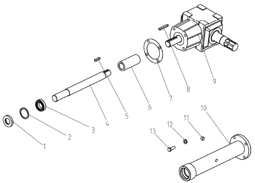
1 |
GB13871-94 |
GB13871-94 |
GB13871-94 |
GB13871-94 |
GB13871-94 |
GB13871-94 |
Oil seal 35×62×10 |
1 |
|
2 |
GB893.1-86 |
GB893.1-86 |
GB893.1-86 |
GB893.1-86 |
GB893.1-86 |
GB893.1-86 |
Circlip 62 |
1 |
|
3 |
GB/T276-94 |
GB/T276-94 |
GB/T276-94 |
GB/T276-94 |
GB/T276-94 |
GB/T276-94 |
Bearing 6007 |
1 |
|
4 |
EFGC100.133 |
EFGC120.133 |
EFGC130.133 |
EFGC140.133 |
EFGC150.133 |
EFGC170.133 |
Shaft |
1 |
|
5 |
GB1096-79 |
GB1096-79 |
GB1096-79 |
GB1096-79 |
GB1096-79 |
GB1096-79 |
Key A10x40 |
1 |
|
6 |
EFGC120.132 |
EFGC120.132 |
EFGC120.132 |
EFGC120.132 |
EFGC120.132 |
EFGC120.132 |
Connected sleeve |
1 |
|
7 |
EFGC120.131 |
EFGC120.131 |
EFGC120.131 |
EFGC120.131 |
EFGC120.131 |
EFGC120.131 |
Paper gasket |
1 |
|
No. |
EFGCH-105 |
EFGCH-125 |
EFGCH-135 |
EFGCH-145 |
EFGCH-155 |
EFGCH-175 |
Name & Specifications |
QTY |
|
8 |
GB1096-79 |
GB1096-79 |
GB1096-79 |
GB1096-79 |
GB1096-79 |
GB1096-79 |
Key A10x70 |
1 |
|
9 |
XH50.300Z.02 |
XH50.300Z.02 |
XH50.300Z.02 |
XH50.300Z.02 |
XH50.300Z.02 |
XH50.300Z.02 |
Gearbox assembly |
1 |
|
10 |
EFGC100.018 |
EFGC120.018 |
EFGC130.018 |
EFGC140.018 |
EFGC150.018 |
EFGC170.018 |
Shaft tube weldment |
1 |
|
11 |
ZBT 32001.3-87 |
ZBT 32001.3-87 |
ZBT 32001.3-87 |
ZBT 32001.3-87 |
ZBT 32001.3-87 |
ZBT 32001.3-87 |
Retainer |
2 |
|
12 |
GB93-87 |
GB93-87 |
GB93-87 |
GB93-87 |
GB93-87 |
GB93-87 |
Plain washer 12 |
4 |
|
13 |
GB5783-86 |
GB5783-86 |
GB5783-86 |
GB5783-86 |
GB5783-86 |
GB5783-86 |
Hex. head bolt M12x35 |
4 |

